EAGLE FLO PUMPS, INC.
U. S. A.
Requesting quote : Telephone ( 201 ) 438 8595 Fax : ( 201 ) 438 8551
email: quote@eagleflopump
Email: eagleflopump@gmail.com
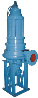
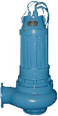
Sizes are from 2 inches (50 mm) up to 16 inches (400 mm) in diameter
with a capacity ranging from 250 GPM ( 60 m3/hr ) to 9000 GPM (2100 m3/hr)
and head from 20 feet (6 m) up to 165 feet (50 m).
******************************************************************************************************************************
This pump operates by circulating oil from the mechanical seal chamber by the channels outside of the body of the pump, and back by the other side of the channel, to the upper portion of the mechanical seal chamber.
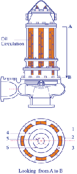
The number of channels will depend on the pump size:
1. 2 way channel directions
2. Outer motor housing flange
3. Motor housing
4. Stator
5. Shaft
6. Rotor
**************************************************************************
SPECIFICATIONS for
Sewage Lift Stations
Shall be furnished complete with all the necessary equipment.
This includes : Pumps, Floating Switch Level Controls, Discharge Base with Bottom Rail
Supports, Upper Rail Supports, Lifting Chains, Pump Hatch Cover Door, Siring Channel,
NEMA 4 Junction Box Control and NEMA 3R Weather Proof Control Panel.
Pumps and Motors
Each pump shall be of the needed submersible type with capacity __________ GPM
( ___________ m3/hr) and Total Dynamic Head of _________ Feet ( _______ Meters ) .
The Pump and Motor shall be designed to operate over the full range of the curve.
Motors shall be designed to be non-overloading over the full curve, and with class H
insulation, 3 phase, 50 or 60 Hz, 220,300, 380, 400, 460 or 575 volts at__________ RPM.
LIQUID TEMPERATURE 160ºF Intermittent
The pump motor shall be of the sealed submersible type with class-H insulation for
operation.
The stator winding, rotor and bearings are to be mounted in sealed submersible type
housing.
This housing shall be filled with high dielectric oil to give superior heat transfer and
longer bearing life {the thermal conductivity of oil is seven (7) times better than air}.
The oil shall travel outside the housing, through the channel, and return back to outside
the housing {as the rules stated cold oil dropped down and warm oil traveled upward}.
• Motor shall be securely held in place with a removable ring and threaded fastened so that it may be easily removed in the field without the use of heat of a press of special tools.
MOTOR HOUSING
Cast Iron ASTM A-48 Class 25 .
Or Cast Iron with 2 to 3 % Nickel Content
Outside of the motor housing a cast / welded steel channel shall be attached to the body of the motor housing. The number of channels will be based on the size and model of the pump. Channel shall has a two way directions.
These channels will let the oil from the Mechanical Seals housing to flow up and down for cooling purposes .
The pump should not require cooling water jackets or auxiliary cooling system (for protection of the motor. Water jacket not always guaranteed for good operation because of existing clogging problems.)
Dependent upon, of use of, water jackets for supplemental cooling should be avoided.
CASING
Cast Iron ASTM A-48 Class 25 Or Cast Iron with 2 to 3 % Nickel Content
EXTENDED FLANGED An extended flanged neck at the inlet of the
INLET NECK Casing will be part of the Casing to provide a positive suction for the pump.
At the middle of the inlet neck, the shut-off of all pumps shall take place ( Lowest Liquid Level at the Wet well ).
This will be the SHUT-OFF LEVEL for all Pumps .
Pump Casing
Shall be supplied with Cast Iron ASTM A-48 Class 25
Wear Ring
---------- OR -------------------
Stainless Steal 304 Grade
SEAL PLATE
Cast iron ASTM A-48 Class 25
IMPELLER
Impeller shall be 2 vanes, and shall be of sufficient size to pass solids of (_100__ mm).
Pump shall be capable of handling raw, unscreened sewage with non-clog type impellers.
IMPELLER Design
Two Non-Clog vanes, with back vanes Statically and Dynamically Balanced
Material Cast iron ASTM A-48 Class 25
----------------- OR -------------------
Cast Iron with 2 to 3 % Nickel Content
Stainless Steel 304 is Optional
Bronze M-3431A is Optional
MOTOR
The pump and motor are to be specially designed so that they may be operated in a dry well installation without any surrounding liquid or using any auxiliary cooling system.
MOTOR Classifications Class H insulation with 1.23 Service Factor .
Cooling
Motor housing contains cooling oil required to cool motor and lubricate all Bearings,
Upper and Lower .
Mineral type oil do not do any harm to environment.
( Thermal Conductivity of Oil is SEVEN - 7 - TIMES Better than Air ) .
THRUST BEARINGS Ball
Corner contacting thrust ball bearing adopted for shaft extension, which can stand
bi -axial load and larger radial load. Single line of Radial Ball Bearing adopted for non-shaft extension bearing.
RADIAL BEARINGS Permanent lubrication
ELECTRIC MOTOR
Stator
Iron core of Stator and Rotor are laminated with steel plates in a high magnetic
conductance and less loss.
Stator Winding and Insulation are made of materials with high temperature
resistance and superior insulation performance.
Stator is immersed in a high temperature lacquer for insulation and heat dissipation.
Rotor
Aluminum product made with cage construction; iron core sleeved on the shaft by
heat . A synchronous grooves are adopted for excellent start and operating
performance .
End Cover
Made out of high strength cast iron ASTM A-48 Class 25, frame base welded
with steel plates to guarantee the strength and flow.
THREE PHASE
Required external overload protection
HEAT SENSOR
Conductor equipped for the Electric Motor and shall be included .
If the pump motor reached the designed class H insulation temperature,
the pump motor will be SHUT-OFF automatically .
MECHANICAL SEALS
Pump shall have Dual Mechanical Seals Cartridge Type.
Chamber
shall be Cast iron ASTM A-48 Class 25 .
MECHANICAL SEALS
Metal parts shall be stainless steel.
Materials
Tungsten Carbide / Silicon Carbide
Dual cartridge type located in ONE chamber with upper and lower seal,
{ Seals Shall be Tungsten Carbide / Silicon Carbide } separated by a metal plate .
Propeller
Shall be installed between both seals without any screws and should be held in place regardless to any condition caused to the pump as a whole.
The Mechanical Seal Chamber propeller is located at the middle of the plate.
Its duty is to push the oil downward or upward ( directions of the flow of the oil is controlled by the design of the propeller through the channel and back by the other
side of the channel down to the mechanical seal chamber.
The channel will help cool the oil pushed by the impeller outside of the body of the pump .
{{ The advantage of this design is to put this pump at work in a wet well as well as in a dry well installation, even if the ambient temperature in the dry well reaches or
exceeds the 50º C .
This pump is capable to run under at any possible condition (wet or dry ), and without damaging any component }} .
SEAL FAILURE
Conductor Shall be installed in the Mechanical Seal chamber .
If one of the Mechanical Seal failed, the conductor will energized the Alarm bell and
Light and provide warning to the contractor.
This will mean that, the mechanical seal shall be replaced as soon as possible.
SHAFT
Made of stainless steel 304 with high mechanical strength and corrosion resistance.
POWER CORD CABLE
Electric power cord shall have an outer jacket which is resistant to oil and other materials normally found in sewage, power cord is to be sealed, not only by use of a cord grip, but shall have individual conductors sealed into the cord cap assembly with epoxy sealing compound.
Thin epoxy seal shall be repeated where the conductors enter the motor from the connection box which is mounted on top of the motor housing.
The cord cap and connection box shall each be sealed with an O-Ring. This will provide a double sealed, watertight power cord entry through which liquid can not enter the motor by following individual conductors inside the insulation.
CABLE ENTRY
Pressure grommet for sealing and strain relief with internal epoxy potted.
Cable is 25 feet of total cable length as standard.
POWER CABLE
4 Conductor, Copper Strands type SO for three phase
RINGS
Are “O“ type for sealing between frame, base, end cover,inner end cover and external end cover.
NOTE. “ O “ Rings can’t be used repeatedly; once, the pump dismantled a new “ O “ Rings should be used.
HARDWARE
All pump fasteners shall be 304 Stainless steel
PAINT
Air dry enamel, to prevent corrosion and long lasting .
FLOAT SWITCH CONTROL
Shall be Normally open, Mercury type, and shall be mounted at a maximum lower level of pump inlet flanged level as a Shut-Off Level for all pumps.
HHA - High High Alarm Level (Option)
HA - High Alarm Level
P4R- Pump No. 4 Running Level
P3R- Pump No. 3 Running Level
P2R- Pump No. 2 Running Level
P1R- Pump No. 1 Running Level
A- is the shut off level for all pumps.
![]()
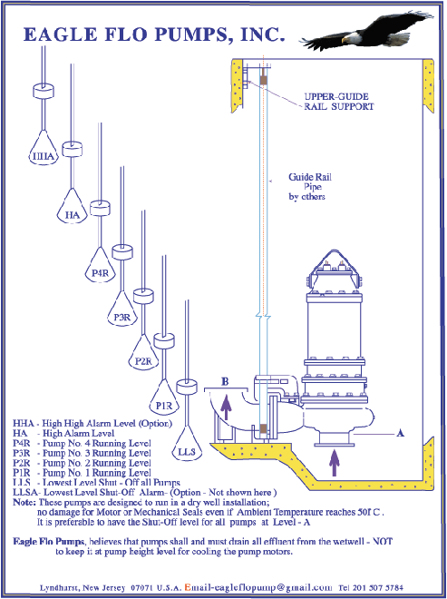
Sump Level Controls:
Sealed float type mercury switches shall be supplied to control sump level and alarm signal.
The mercury tube switches shall be sealed in a solid polyurethane float for corrosion and shock resistance. The support wire shall have a heavy neoprene jacket and a weight shall be attached to cord above the float to hold the switch in place in sump. Weight shall be above the float to prevent sharp bends in the cord when the float operate under water.
The float switches shall hang in the pump supported only by the cord that is held to the NEMA 4 junction box or the wiring channel. Three(3) float switches shall be used to control level. Duplex pump lift station) Two for pump turn-on, and one for pump turnoff, a fourth switch shall be provided for alarm control. Furnish and install the following alarm system.
1- a high effluent level alarm
2- alarm flashing light (with bell)
Flashing light shall be supplied in a separate NEMA 3 enclosure for mounting at the control box.
Alarm light shall glow dim at all times except under alarm conditions.
Then it shall glow bright and flash.
Optional- Fifth float switch for:
High - High Alarm Level Alarm
-OR-
Low level liquid alarm
Protection
Seal failure shall be included.
Heat sensor shall be included.
Sump Level Rise
Lower mercury switch shall first be energized, then upper level switch shall next energize and start lead pump.
With lead pump operating sump level shall lower to low switch turn off setting and pump shall stop.
Alternating relay shall index on stopping of pump so that lag pump will start on next operation.
If sump level continue to rise when lead pump is operating, override switch shall energize and start lag pump.
Both lead and lag pump shall operate together until low.
Control Panel:
Control panel shall have NEMA 3R weather proof enclosure.
A lock hoop shall be provided on door.
A circuit breaker shall be provided for each pump and a magnetic starter with 3
lag overload protection for three phase operation.
An alternating relay shall be provided to alternate pumps non each successive
cycle of operation.
Starters shall be provided to alternate pumps on each successive cycle of operation.
Starters shall have auxiliary contacts to operate both pumps on override condition.
An interlock relay shall be provided it automatically reconnect the control circuit in case of circuit breaker trip on one pump.
H-O-A (Hand-Off-Automatic) switches and run lights shall be supplied for each pump.
A terminal strip shall be provided for connecting pump and control wires.
Additional terminals shall be provided to connect the alarm.
A transformer shall be supplied to give a 24 volts control circuit.
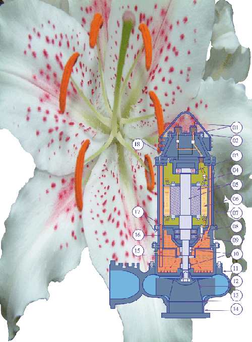
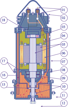
02. Pump Handle
03. Bearing upper single row, ball type
04. Sensor assembly Heat type
05. Shaft 304 stainless steel, with Rotor
06. Stator
07. Channels for Mechanical Seal Oil circulation.
08. Sensor assembly,Seal Failure
09. Bearing Lower double row, ball radial load and thrust
10. Mechanical seal assembly
11. Pump Volute
12. Impeller, two vanes with solids handling capabilities
13. Pump volute Wearing ring
14. Pump inlet neck for positive suction
15. Propeller for oil circulation
16. Oil circulation for Mechanical Seal Chamber.
17. Dual O- Rings
18. Mechanical Seals oil fill inlet